Nordic nRF52832 BLE 5.0 module with ipex slave, master, master-slave, beacon module
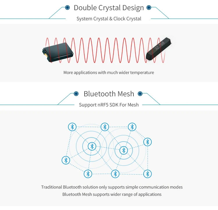
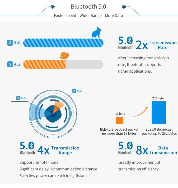
RF-BM-ND04I is an RF module based on Nordic BLE SoC nRF52832 with ARM? Cortex?-M4 32-bit processor. It integrates a 32.768 kHz and a 32 MHz crystal, an LC filter, an antenna matching and an IPEX antenna interface. It features low power consumption, small size, robust connection distance, and rigid reliability. It supports BLE stack v5.0 and can be preprogrammed with a serial interface communication protocol for simple programming. 1.27-mm pitch stamp stick package for easy assembling and cost-effective PCB design. RF-BM-ND04I is pin-to-pin compatible with RF-BM-ND04CI.
Parameters of RF-BM-ND04I
Chipset | nRF52832QFAA |
Supply Power Voltage | 1.7 V ~ 3.6 V, recommended to 3.3 V |
Frequency | 2402 MHz ~ 2480 MHz |
Transmit Power | -20.0 dBm ~ +4.0 dBm (typical: 0 dBm) |
Receiving Sensitivity | -96 dBm |
GPIO | 29 |
Crystal | 32 MHz, 32.768 kHz |
RAM | 64 KB |
Flash | 512 KB |
Package | SMT Packaging |
Frequency Error | ±20 kHz |
Dimension | 24.8 mm x 15.0 mm x (2.3 ± 0.1) mm |
Type of Antenna | IPEX connector / half-hole antenna interface |
Operating Temperature | -40 ℃~ +85 ℃ |
Storage Temperature | -40 ℃~ +125 ℃ |


Recommended Footprint

Pin Attributes

Pin Functions of RF-BM-ND04I
Pin | Name | Chip Pin | Pin Type | Description |
1 | GND | GND | GND | Ground |
2 | ANT | ANT | ANT | Antenna interface |
3 | GND | GND | GND | Ground |
4 | GND | GND | GND | Ground |
5 | VCC | VCC | Power | Power supply 1.7 V ~ 3.6 V, Recommend 3.3 V |
6 | P21 / RST | P0_21 / RESET | I/O | Reset, active low. |
7 | P22 | P0_22 | I/O |
|
8 | P23 | P0_23 | I/O |
|
9 | P24 | P0_24 | I/O |
|
10 | P25 | P0_25 | I/O |
|
11 | P28 | P0_28 / AIN4 | I/O |
|
12 | P29 | P0_29 / AIN5 | I/O |
|
13 | P30 | P0_30 / AIN6 | I/O |
|
14 | P26 | P0_26 | I/O |
|
15 | P27 | P0_27 | I/O |
|
16 | P02 | P0_2 / AIN0 | I/O |
|
17 | P03 | P0_3 / AIN1 | I/O |
|
18 | P04 | P0_4 / AIN2 | I/O |
|
19 | P05 | P0_5 / AIN3 | I/O |
|
20 | P06 | P0_6 | I/O |
|
21 | P07 | P0_7 | I/O |
|
22 | P08 | P0_8 | I/O |
|
23 | P09 | P0_9 | I/O |
|
24 | P10 | P0_10 | I/O |
|
25 | P11 | P0_11 | I/O |
|
26 | P12 | P0_12 | I/O |
|
27 | P13 | P0_13 | I/O |
|
28 | P14 | P0_14 | I/O |
|
29 | P15 | P0_15 | I/O |
|
30 | P16 | P0_16 | I/O |
|
31 | SWDIO | JTAG SWD | I/O | Serial wire debug I/O for debug and programming |
32 | SWCLK | JTAG CLK | I/O | Serial wire debug clock input for debug and programming |
33 | P17 | P0_17 | I/O |
|
34 | P18 | P0_18 | I/O |
|
35 | P19 | P0_19 | I/O |
|
36 | P20 | P0_20 | I/O |
|


