Product Description
RF-BM-2652B1 CC2652R Multi-protocol 2.4 GHz Wireless Module Bluetooth 5 low energy Module
RF-BM-2652B1 is an RF module based on TI lower-power CC2652R SoC. It integrates a 48 MHz crystal and a 32.768 kHz crystal, 352 KB of in-system Programmable Flash, 256 KB ROM, 8 KB of Cache SRAM, 80 KB of ultra-low leakage SRAM. Its ARM? Cortex?-M4F core application processor can operate at an extremely low current at flexible power modes. Its 2.4 GHz RF transceiver is compatible with Bluetooth 5 Low Energy and IEEE 802.15.4 PHY and MAC. It features small size, robust connection distance, and rigid reliability.
Parameters of RF-BM-2652B1
Chipset | CC2652R |
Supply Power Voltage | 1.8 V ~ 3.8 V, 3.3 V is recommended |
Frequency | 2402 MHz ~ 2480 MHz |
Maximum Transmit Power | +5.0 dBm |
Receiving Sensitivity | -100 dBm @ 802.15.4 (2.4 GHz) -105 dBm @ Bluetooth 125 kbps (LE Coded PHY) |
GPIO | 31 |
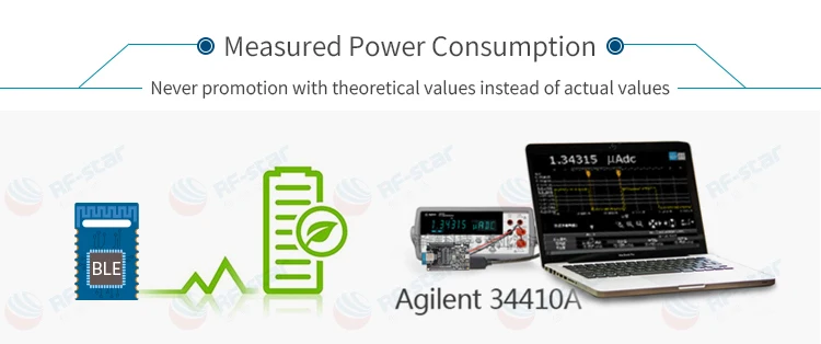
Power Consumption | RX current: 6.9 mA TX current: 7.3 mA @ 0 dBm 9.6 mA @ 5 dBm MCU 48 MHz (CoreMark):3.4 mA (71 μA/MHz) Sensor Controller:30.8 μA @ Low Power-Mode, 2 MHz 808 μA @ Active-Mode, 24 MHz Standby: 0.94 μA Shutdown: 150 nA |
Support Protocol | Bluetooth 5 Low Energy,ZigBee, Thread, IEEE 802.15.4m 6LoWPAN |
Crystal | 48 MHz, 32.768 kHz |
Package | SMT packaging (Half hole) |
Communication Interface | UART, SPI, I2C, I2S, ADC |
Dimension | 23.50 mm × 17.03 mm × (2.2 ± 0.1) mm |
Type of Antenna | PCB antenna |
Operating Temperature | -40 ℃~ +85℃ |
Storage Temperature | -40 ℃~ +125 ℃ |


Recommended Footprint

Pin Attributes

Pin Diagram of RF-BM-2652B1
Pin | Name | Function | Description |
1 | P00 | GPIO | GPIO, Sensor Controller |
2 | P01 | GPIO | GPIO, Sensor Controller |
3 | P02 | GPIO | GPIO, Sensor Controller |
4 | P03 | GPIO | GPIO, Sensor Controller |
5 | P04 | GPIO | GPIO, Sensor Controller |
6 | P05 | GPIO | GPIO, Sensor Controller, high-drive capability |
7 | P06 | GPIO | GPIO, Sensor Controller, high-drive capability |
8 | P07 | GPIO | GPIO, Sensor Controller, high-drive capability |
9 | P08 | GPIO | GPIO |
10 | P09 | GPIO | GPIO |
11 | P10 | GPIO | GPIO |
12 | P11 | GPIO | GPIO |
13 | P12 | GPIO | GPIO |
14 | P13 | GPIO | GPIO |
15 | P14 | GPIO | GPIO |
16 | P15 | GPIO | GPIO |
17 | JTAG_TMSC | JTAG_TMSC | JTAG TMSC, high-drive capability |
18 | JTAG_TCKC | JTAG_TCKC | JTAG TCKC |
19 | P16 | GPIO | GPIO, JTAG_TDO, high-drive capability |
20 | P17 | GPIO | GPIO, JTAG_TDI, high-drive capability |
21 | P18 | GPIO | GPIO |
22 | P19 | GPIO | GPIO |
23 | P20 | GPIO | GPIO |
24 | P21 | GPIO | GPIO |
25 | P22 | GPIO | GPIO |
26 | P23 | GPIO | GPIO, Sensor Controller, Analog |
27 | P24 | GPIO | GPIO, Sensor Controller, Analog |
28 | P25 | GPIO | GPIO, Sensor Controller, Analog |
29 | P26 | GPIO | GPIO, Sensor Controller, Analog |
30 | P27 | GPIO | GPIO, Sensor Controller, Analog |
31 | P28 | GPIO | GPIO, Sensor Controller, Analog |
32 | P29 | GPIO | GPIO, Sensor Controller, Analog |
33 | P30 | GPIO | GPIO, Sensor Controller, Analog |
34 | VDD-_EB | VDD | Power Supply: 1.8 V ~ 3.8 V, recommend to 3.3 V |
35 | GND | GND | Ground |
36 | NRESET | RESET---_N | Reset, active-low. No internal pullup |


